Technical Documents
- Regarding the motor burnout protection method
- Fan Installation Method
- Classification of protection grades that represent waterproof capacity
- Fan Selection
- Hydrostatic Pressure and Airflow Characteristics
- Fan Wind Speed Distribution Characteristics
- Problems with magnetic flux leakage and countermeasures
- Causes of noise generation due to the number of blades, frame shape, and fan mounting part shape
- Impact Strength
- noise
- Parallel operation and series operation
- Prevention of start-up and rotation problems due to mutual interference
- Optional, change of static pressure and airflow characteristics by attaching a filter kit
- Fan Sensors
- Fan motor lifespan
- Terminology
- Security Export Management System
Regarding the motor burnout protection method
If the fan is restrained while it is energized for some reason, the current density of the winding coil itself will increase, and the winding temperature will also increase, so it is safer to take some kind of winding burnout prevention protection.
There are two types of protection methods, which are described below.
1.Impedance protection method
This method utilizes the impedance (AC resistance) of the motor windings to limit the winding coil’s saturation temperature during a stall condition to below the burnout threshold.
It does not incorporate a dedicated protection circuit, but is instead designed such that the winding temperature rise under stall conditions at room temperature (25°C) remains within 125°C.
In terms of safety standards, this method adheres to UL requirements and is generally applied to fans with frame sizes up to 120 mm square.
2.Thermal protector method
This method incorporates a thermal relay inside the motor, which disconnects the power supply when the winding temperature approaches the burnout threshold.
The thermal relay is connected in series with the coil and operates by detecting the coil’s temperature. It typically uses a bimetal mechanism.
This protection method is mainly applied to larger fans (typically 127 mm square or 150 mm diameter or more) that cannot be protected using the impedance method due to design constraints.
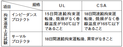
| Indicated Temperature [°C] | Cut-off temperature [°C] | Reset Temperature [°C] |
|---|---|---|
| 120 | 120±5 | 85±15 |
| 135 | 135±5 | 95±15 |
| 140 | 140±5 | 100±15 |
| 145 | 145±5 | 105±15 |
Due to factors such as temperature detection inaccuracies of the thermal relay and the delay in heat transfer from the coil, there may be a time lag in operation. Therefore, activation generally occurs near the temperatures indicated above.
Stall Condition Temperature Rise Test (at 25°C)
Safety Standards, Insulation Classes, and Maximum Permissible Temperatures
| Safety Standard | Insulation Class | Maximum Permissible Temperature |
|---|---|---|
| UL/CUL | Class A | 105°C |
| TÜV | Class E | 120°C |
| VDE | Class E | 120°C |
| CQC | Class E | 120°C |
| S-JET | Class E | 120°C |
| 一般 | Class E | 120°C |
| CSA | Class B | 130°C |
Fan Installation Method
When installing the fan onto equipment, refer to the “Mounting Hole Dimensions” diagram provided on each product specification page and drill the mounting holes accordingly.
Note: The shape of the mounting holes may differ between the intake (suction) side and the exhaust (discharge) side, depending on the product.
Fan Mounting Direction
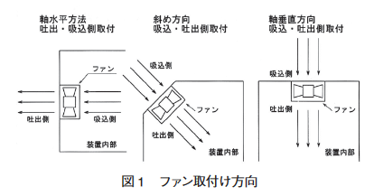
The fan can be mounted in any direction: horizontal, vertical, or diagonal.
In addition, it can be installed on either the discharge side or the suction side.
Fan installation method
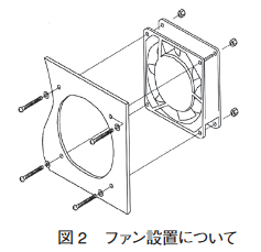
There are two types of fan installation methods. There are two types: 1. flange mounting on one side and 2. flange mounting on both sides using through bolts
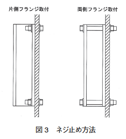
When installing, make sure to install on a strong steel plate that is not subject to vibration or shock.
In addition, when mounted on a thin steel plate (less than 1 mm), the vibration of the fan itself is designed to be minimal, but it still has some vibration, so in some cases it may resonate and affect the life or generate resonant sound, so it is recommended to install it in a solid place as much as possible.
In addition, mounting screws are not included, so please prepare screws suitable for each product.
Tightening torque
Single-sided flange mounting is recommended.
In the case of double-sided flange installation, pay attention to the tightening torque of the screw.
The appropriate tightening torque is 0.44 N·m (M4).
Please note that tightening with more torque than necessary may deform the frame and cause problems such as internal contact.
About the mounting position
Keep the front of the fan opening as wide as possible to avoid sudden changes in the direction of the airflow.
As a guide, keep the distance between the fan opening surface and the cooled body at least 1/2 of the blade diameter.
Please note that the interval may be less than that, as it may impair the cooling effect.
When installing a fan with a sensor, please be careful about the mounting position as it may malfunction if there is something that causes large electromagnetic induction nearby.
Power supply method
There are two types of power supply methods.
- Terminal Connections
- Lead wire connection
The connection method differs depending on the model, so please check the catalog before specifying.
In the case of the terminal connection type, the plug cord is not included.
Optional Installation
When integrating the fan into the device, consider safety and install finger guards in places where there is a risk of human touch.
In addition, in an environment where dust is flying, dust may enter the inside of the device or the inside of the fan through the opening of the fan, which may cause a malfunction or affect the life of the device, so it is recommended to install a filter kit.
It can prevent dust from entering the interior and improve reliability.
Classification of protection grades that represent waterproof capacity
1.Moisture-proof
The moisture-proof specification was developed for showcases and freezers used in Japan.
The moisture-proof level is equivalent to IPX1~X2 because of the open type motor.
2.Waterproof ability
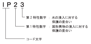
Although an “IP code” is used to express the waterproof ability, it was originally a standard for testing the waterproof ability of enclosure boxes and was not applied to rotating equipment. Due to the fact that IP codes are defined in the EN/IEC standard, industrial equipment manufacturers are required to use CE marking for marketing in Europe, and the EN/IEC standard is also required at the level of each component inside the equipment, and the fan is also required due to the fact that it is expressed at the IP level in the standard.
The following shows how to read the IP code.
The following table shows the IP code definitions.
1st characteristic: degree of protection against the ingress of solid foreign matter
| IP Code | Definition of equipment protection | Definition of human protection |
|---|---|---|
| ー | No protection | No protection |
| 1X | Protects against solids larger than 50mm | Back |
| 2X | Protects against solids larger than 12mm | finger |
| 3X | Protects against solids larger than 2.5mm | tool |
| 4X | Protects against solids larger than 1.0mm | Wire |
| 5X | Dust protection | Wire |
| 6X | dustproof | Wire |
Second property: the degree of protection against water ingress
| IP Code | Type of protection | definition |
|---|---|---|
| ー | No protection | Unprotected stuff |
| X1 | Splash-proof I. | Water droplets falling from the vertical do not have a harmful effect |
| X2 | Splash-proof II | Water droplets falling within 15 degrees of vertical detrimental effects |
| X3 | Rainproof | Rainfall in the vertical to 60 degree range without harmful effects |
| X4 | Anti-lash type | Water splashes from any direction that do not have harmful effects |
| X5 | Jet-proof type | Direct jets of water from any direction that do not have harmful effects |
| X6 | Water-resistant | Water does not enter the interior even if it receives a direct jet of water from any direction |
| X7 | Immersion-proof | Even if it is submerged in water under specified conditions, water does not enter the inside. |
| X8 | Underwater form | Those that can be used by constantly submerging in water at specified pressures |
| X- | Moisture-proof | Moisture-proof type: Can be used in humidity above 90% relative humidity |
Fan Selection
This section explains how to obtain the required airflow characteristics for general equipment.
- Clarify the allowable temperature and design value of the device, and clarify the design value of the internal temperature of the device to be below °C.
- The amount of heat generated by the
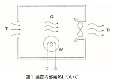
input voltage and current consumption of each component in the calorific value calculator inside the device is calculated. - Calculate the required air volume by the formula for calculating the required air volume
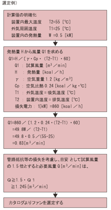
- Consideration of system impedance (pipeline resistance)The
system impedance in the device is unique to the device, which is determined from the density rate and pipeline shape of each component in which the device is configured, but if the air flow is obstructed, it becomes a loss, and this pressure loss is called system impedance.
The system impedance can be calculated by a formula, but it is difficult to obtain the internal pipeline volume by calculating the internal pipeline volume from the dimensions because it is necessary to know the constant specific to the device, so in general, a fan with a maximum air volume of 1.3 times ~ 2 times the required air volume is selected.
Since the pressure loss varies depending on the density rate inside the device, the required air volume is approximately the required air volume when the pipeline resistance is small: 1.3 times, when the pipeline resistance is medium: 1.5 times, and when it is large: 2 times. - System impedance calculation formula
P=KQn
P:Drop pressure (Pa)
K:Device-specific constant
n:Constant
n = 1 laminar flow
n = 2 turbulent flow * normal n = 2 determined by air flow - Fan selection: Select a fan from
the calculated required air volume Q and the fan size to be installed
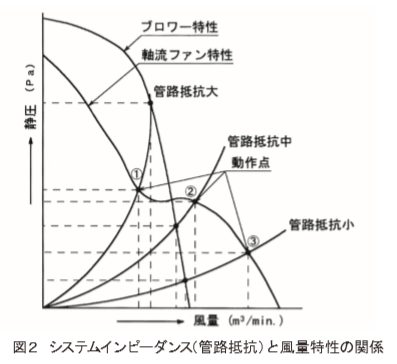
Differences between axial fans and blower fans Due to the nature of axial fans and blower fans, there is a significant difference in the hydrostatic pressure single air volume characteristic curve.
Axial fans have the property that a high air volume can be obtained when the pipeline resistance is small (see Fig. 2), and the air volume obtained decreases greatly as the pipeline resistance increases.
On the other hand, even if a motor equivalent to an axial fan is used, a high air volume cannot be obtained, and the air volume obtained is small, but even when the pipeline resistance is large, the air volume obtained does not have an extreme drop and the air volume is maintained.
Hydrostatic Pressure and Airflow Characteristics
The Ps-Q characteristic curve listed in each specification is the average value of the actual measured data and is not a guaranteed value, so please use it as a guide for fan selection when considering equipment design.
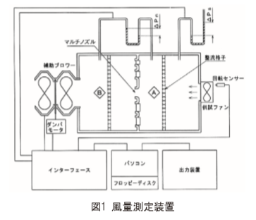
Measurement method of static pressure and airflow characteristics Currently, most manufacturers in the fan motor industry use the multi-nozzle double-chamber method based on “AMCA STANDARD 210-85” in the United States. Since it is not possible to obtain accurate values in the fine air volume area, the multi-nozzle double chamber method according to the “AMCA STANDARD 210-85” standard, which can accurately measure the fine wind volume area described in JIS, is adopted. Some products use wind tunnel measurements. The measurement method is shown below.
1.Wind tunnel measurement
For wind tunnel measurement, a pitot tube is installed in the center of the cylindrical wind tunnel, a fan is attached to the end of the wind tunnel, and suck in from the damper side and discharged through the pitot tube. Pitot tubes are generally measured in the center of the wind tunnel where the pipeline resistance is low, and the air volume is higher because it is measured at the fastest wind speed with the least pipeline resistance. Compared to double-chamber measurement, it is about 2~3% higher.
2.Multi-nozzle double chamber measurement
In the multi-nozzle double-chamber measurement, the maximum static pressure is measured by first creating a sealed environment in Chamber A with the multi-nozzle fully closed, and then the pressure in the chamber is automatically controlled by opening and closing the auxiliary blower and damper to create a state of 0 air resistance and average the air flow to measure the maximum air volume. By dividing the maximum air volume by the specified number of measurement points (10 point measurement in our company) from the maximum air volume measured, and dividing it into 10 places if it is 10 point measurement, the state of 0 air resistance at each air volume point is divided into 10 places, and the auxiliary blower and damper are opened and closed in the same way as at the time of maximum air volume measurement. By measuring and calculating the pressure difference of the pressure gauge placed in front and behind the multi-nozzle, it is measured in conjunction with a computer.
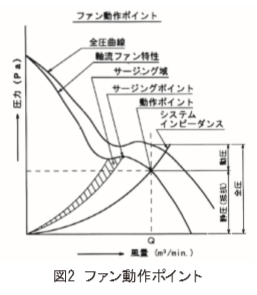
Fan Operating Points As mentioned in the fan selection, if you try to flow air in a pipe in a certain direction, air resistance will occur in the opposite direction. This blower resistance is related to the square of the air volume, which is called the “system impedance”, and the intersection of the fan characteristics under static pressure and the system impedance is the “operating point”. In addition, there is an area where it is better not to operate the fan if possible, but this area is called the “surging area”, and the point just before entering the surging area is called the “surging point”. From this point, the area until the static pressure characteristics drop down is the surging area. This series of phenomena is called the “surging phenomenon.” This phenomenon occurs when the system impedance is applied, the pressure pulsates in a certain area, and the required amount of air is not obtained, and in the small fan we handle, the static pressure-air volume characteristics become unstable and it fits at a level that has a slight impact on noise. If a surging phenomenon occurs, vibration and noise will be emitted, and operation will not be able to continue, and the fan may be damaged.
Next, the air volume is calculated by the following formula.
Q = 60 AV
Q: Air volume (m3/min)
A: Cross-sectional area of nozzle π D2 / 4 (m)
V: Average air speed at the nozzle outlet
V = 2・△Pn/γ (m/sec)
γ: Specific gravity of air (kg/m3)
[At 20°C 1 atm γ = 1.2]
△Pn: Dynamic pressure (Pa)
Fan Wind Speed Distribution Characteristics
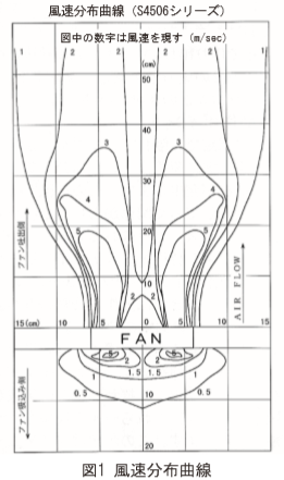
The curve in Figure 1 shows the wind speed distribution of the axial fan.
As can be seen from Figure 1, the wind speed on the intake side and the discharge side are different.
The features are as follows.
- The wind speed distribution area on the suction port side is weak, and it tries to suck in from a short distance to a wide angle.
- The wind speed distribution area on the outlet side has a long reach distance and generates strong wind speed almost in a straight line.
- The wind speed is highest on the outer periphery of the blades, and a high wind speed zone is generated in a straight line, and it diffuses to the surroundings by sending it out over the entire blade surface.
Problems with magnetic flux leakage and countermeasures
I think that the problem caused by magnetic flux leakage is usually due to the influence of shaking of the display image, but since the fan is a single-phase two-pole coil induction motor, the strongest magnetic flux is generated in the part where the motor coil is wound, but the magnetic flux always flows from the north pole to the south pole. The magnetic flux is generated in an elliptical motion from the winding coil that generates the strongest magnetic flux to the winding coil part of the anide. Think back to the time when you put a bar magnet on the iron sand on the underlayment. The countermeasures are as follows.
- Keep your distance
- Cover and shield the outer perimeter of the fan with a steel plate
- Change the mounting position or direction (angle)
- By swapping the polarity of the input terminals, the direction of magnetic polarity with the polarizing coil is changed
- Shielding between the polarizing coil and the fan
The above measures may be effective, but they may not be effective depending on the usage situation.
Causes of noise generation due to the number of blades, frame shape, and fan mounting part shape
I will touch on it a little in the noise section, but in the case of axial fans, the noise that has the most impact is the intake and exhaust noise. In particular, it occurs on the outer periphery of the suction side, but the outer periphery of the suction side has a fast peripheral speed and a large area, and the flow rate is large, so the wind flow is random, causing an interference phenomenon and a high sound. The effect is less on the discharge side. The factors can be further subdivided into the following factors.
1.Fan design problems
- Blade shape
- Relationship between the number of frame ribs and the number of blades
- Frame rib and blade (suction) intersection angle
- Frame inner diameter (venturi) shape
- Feather material
2.Problems on the part of the user
- Design shape in front of the fan mounting partUse
a mesh-shaped guard at the fan air intake to ensure that there is no problem with the intersection angle with the fan blades, or take a shape that cuts the wind with dots instead of surfaces as much as possible. - System impedance operating positionIf
there is an operating point in the surge range, the intake noise may be high, so avoid the surging range.
3.Noise when using fans in parallel
In the case of parallel operation, noise may increase due to mutual interference.
For details on how to suppress interference noise, refer to “Parallel and Series Operation”.
Impact Strength
The fan motor uses precision-grade ball bearings, so it must not be subjected to impact. It is difficult to quantify the size of the drop impact, and even if the drop impact is the same distance, the impact applied will be completely different depending on the direction and angle of the fall. We have confirmed the following contents.
1.Single item drop, impact test (bearing impact resistance)
- Test conditions: A wooden board with a thickness of 10 mm is placed on the concrete floor and the fan is allowed to fall naturally.
- Drop Height & Standards
- Drop height 40 mm: No abnormality in the bearing part except for the bearing noise
- Drop height 500 mm: Unusual mushroom due to appearance structure
2.Frame rib strength (between the outer angle of the frame and the motor)
The representative model S4506 series (120×38mm) is shown below.
- Breaking load of 3 ribs: 1373 N (Breaking load of 1 rib: 461 N)
- Converted value to impact force: 3432 m/s2 (rib 1 true: 1152 m/s2)
* Total load of rotor and stator = 400 g
noise
The noise of the fan is expressed by the A characteristic [dB(A)] of the hearing correction circuit, which is said to be close to hearing. There are various causes of noise, such as intake and exhaust noise caused by fan blowing, mechanically generated bearing noise, electrically generated magnetic sound, resonant or reverberating sound generated by mounting the housing, and interference noise generated between other equipment. The intake and exhaust noise in this is proportional to the air volume, so as the air volume increases, the intake and exhaust noise also increases. In addition, the bearing noise tends to increase as the rotation speed increases, and resonance and reverberation to the housing tend to be more likely to occur. The noise emitted by the fan itself has the greatest impact on the intake and exhaust sound, but our fans are designed to suppress noise as much as possible while designing for a high airflow. In addition, noise often depends on the equipment design, and the initial design of the equipment is important, which can greatly affect the noise level. When designing equipment, please pay attention to the following.
- The distance between the fan intake and exhaust vents and the cooled body should be as much as possible within the range allowed by the design.
If you get too close, you will be in a state where almost no air volume will be emitted.
As a guideline, keep the blades at least 1/2 of the outer diameter apart. - As much as possible, avoid designing the fan in such a way that the flow path of the fan bends at a right angle. This will result in a loss of pressure.
In addition, please pay attention to the following points when designing the equipment.
- If multiple fans are installed in parallel and used, the noise may increase due to interference between the fans, but please make sure that the fans are spaced apart or that a divider plate is inserted between the fans.
- When using finger guards and filter kits, wind noise may occur due to interference with spokes or fins, but it can be improved by using spacers and spacing the fan.
Noise Measurement
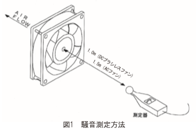
Our noise value (A characterization) is measured at a position of 1.5 m (excluding DC brushless fans) above the centerline of the suction port of the fan. In addition, the noise values shown in the catalog are measured in an anechoic chamber. This measurement method was in accordance with the “Test and Inspection Method for Blowers” of the old JISB8330, but now it has been shifted to the “Noise Level Measurement Method for Blowers and Compressors” of the JISB8346, and the measurement has been changed from 1.5 m to 1.0 m on the centerline of the fan inlet. We have not changed the measurement at 1.5 m due to compatibility issues with the specifications we have issued so far, but we plan to change it eventually. In addition, the noise measurement method among fan manufacturers is not unified, and it is not possible to make a simple comparison on the catalog, so please check the measurement method before comparing.
Relationship between distance and noise value
Since noise propagates in a spherical shape from the center of the sound source and has the property of attenuating in inverse proportion to the square of the distance, the following conversion equation holds, and if the reference noise value is clear, the noise value at different distances can be calculated by calculation. dB = dB 0 + 10 ・ log10 (10/1) 2 dB: Noise conversion value at distance 1 (dB) dB 0: Reference noise value at distance 10 (dB) 10: Reference distance 1: Distance to be converted
Due to the relationship between 10 and 1 in the above conversion formula, it can be seen that if the distance to be converted is constant, the noise increase rate is also constant. For example, to convert a noise value at 1.5 m to a noise value at 1.0 m, an increase of 3.5 (dB) is required. The value obtained by the above formula is at a standard level and may differ from the accurately measured value.
Synthetic noise
The noise value when two or more fans are operated can be calculated by the following equation. dB = 10・log10 (10dB1/10+10dB2/10+10dB3/10…) dB: Synthetic noise value to be determined (dB) dB1: Fan 1 noise value (dB) dB2: Fan 2 noise value (dB)
For example, if two fans are made of synthetic noise and have a noise of 43 (dB), dB
= 10 and log10 (1043 / 10×2) = dB 1 + 3 = 46 (dB),
which is an increase of 3 (dB) from the case of one fan.
In addition, in the case of fans with different noise values, for
example, if the first unit is 43 (dB) and the second unit is 56 (dB), dB = 10 and log10 (1043/10 + 1056/10) = 56.2 (dB),
which is different from the case of the same fan.
This means that fans with different noise levels are mostly affected by fans with higher noise levels. Similarly, when designing equipment, it is necessary to suppress the noise value of the parts with the highest noise value in the equipment.
Parallel operation and series operation
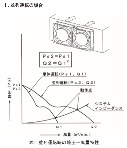
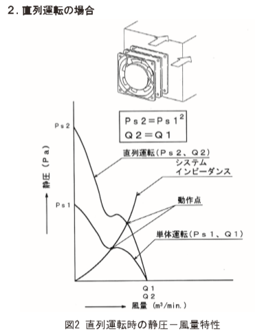
Two fans with the same characteristics can be operated in parallel or in series to change their characteristics. As shown in Fig. 1, the maximum air volume is twice as high as when operating in parallel as when operating a single unit, and in the case of series operation as shown in Fig. 2, the maximum static pressure theoretically changes by a factor of two.
Please note that this does not mean that double the air volume can be obtained by parallel operation of two units, or triple the required air volume by parallel operation of three units, but the operating point of the system impedance will change.
As the airflow increases, the resistance increases by the square, so does the operating point of the system impedance.
Prevention of start-up and rotation problems due to mutual interference
One thing to keep in mind when operating in parallel is that when the system impedance is high, or when operating in close parallel, there may be a phenomenon in which air flow is sucked in from one fan and discharged to the other fan instead of being inhaled from the suction side of the device that must take in the air flow.
This phenomenon occurs due to the competition for air volume between the two motors, which overload the motor and brake the rotation. In this state, if the fan characteristics are low or the start is delayed, the rotation speed will be significantly reduced due to the pull of the other fan, and in the worst case, the fan will rotate in reverse, and the motor may be burned out in prolonged use.
Even in series operation, they interfere with each other and overload the motor, so it is necessary to carefully consider when selecting a fan.
Measures to be taken in parallel operation are as follows.
- Increase fan spacing
- Put a divider between the fans
- In some cases, lowering the system impedance (improving the internal congestion of the device) can be effective, but in other cases it is not effective.
As for measures to take when operating in series, please consider spacing the fans without directly connecting them.
Optional, change of static pressure and airflow characteristics by attaching a filter kit
By attaching the filter kit to the fan, the airflow characteristics are reduced by 2~3%, so it is necessary to consider this when selecting a fan. In addition, there is almost no effect on the finger guards.
When incorporating a fan into a device, it is important to improve safety and reliability by installing options such as finger guards and filters, but it will affect the air blowing resistance, static pressure-airflow characteristics, and noise, so please consider it when considering.
Fan Sensors
In recent years, customer equipment has become smaller and faster, and the number of devices that require forced cooling is increasing.
Since the fan motor is a part and has a lifespan, it is important to set an appropriate replacement time for each device and prevent problems by maintaining it early.
The metal vane type fan sensor is a sensor that attaches a magnet and a pickup coil to the side of the outer shell of the fan motor, detects the disturbance of the magnetic field that occurs when the metal blade passes through, generates an AC signal proportional to the rotation speed, and outputs an alarm when the rotation speed drops below the specified speed.
Fan sensors for DC fan motors output low speed alarms in a similar manner based on rotation signals from internal drive circuits. We also have a lineup of rotation stop sensors with built-in DC fan motors. We have many years of production experience, and the simple circuit configuration is highly reliable, and there are many variations to match the design concepts of various customers.
In order to increase reliability, the relay output type adopts a reed switch enclosed in a glass tube, which is not affected by the installation environment and has a mechanical contact life of more than 100 million times.
Selection of representative fan sensors
- Selection of Normally Open and Normally Closed:
When the fan motor is running normally, select the type whose output is open (N/O) and the type whose output is closed (N/C). Specify “-N/O” or “-N/C” at the end of the model. - Selection of output status when the fan motor is turned onWhen the
rotation speed when the fan motor is turned on, the normal output or the alarm output is good. Good normal output: With start-up delay time timerModel
: T□□□ or T□□□B
Alarm output is good: No start-up delay timerModel
: S□□□ or S□□□D - Selection of output status when the sensor power is turned offNormal
output is good: T□□□ or S□□□D
Alarm output is good: T□□□B or S□□□ - Other Selection Items
- Selection of sensor supply voltage
- Selection of output devices (relays, open-collector types)
- Selection of input/output wire type (lead wire or lead wire terminal with connector)
Standard Definition for Relay Output Sensors
Relay output type sensors with a 1A (1 make) relay are standard.
The type of T-type sensor with a timer with “T□□□B” and a “B” at the end is normally closed until the internal relay drive circuit. Therefore, if a 1A (1 make) relay is attached, the entire sensor will operate as normally closed. In addition, the type excluding the timer function of this circuit is the S-type sensor “Model: S□□□”.
In addition, the T-type sensor with a timer and the “Model: T□□□” type is normally open until the relay is driven, and when a 1a (1 make) relay is attached, the entire sensor operates as normally open. In addition, the type excluding the timer function of this circuit is the S-type sensor “Model: S□□□D”.
Precautions for sensors with start-up delay time timers
All sensors are integrated with a capacitor to accommodate noise margins and instantaneous drops in supply voltage.
Therefore, when the sensor output changes, there is a time lag of less than 3 seconds as an operating delay time. Therefore, please note that the sensor “Model: T□□□B” with a start-up delay time timer also has an operation delay time, and an alarm is output before the sensor is turned on, and after the power is turned on, the signal becomes normal after an operation delay of 3 seconds or less.
How to check the sensor output format
Our products with sensors before 1994 do not have a normally open or normally closed indication on the sensor label. If the sensor type is known by the relay output type, it can be determined by checking whether or not the contacts are conductive when the power is turned off, as can be seen from the above explanation.
T□□□→ Normally open T□□□B → Normally closed S □□□→ Normally closed with no continuity between contacts
T□□□→ normally closed T□□□B with continuity between contacts→ normally open, S□□□→ normally open
Fan motor lifespan
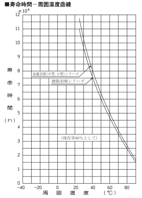
The life of a fan can be roughly divided into the life of the electrical part and the life of the mechanical part.
The fan motor structure consists of a winding, a rotating part, and a bearing frame, and is a simple structure that is less prone to design defects.
If the electrical part is used within the scope of use, there will be no problems in the first place, and in most cases the bearing life of the mechanical part is a factor.
The life of the bearing is one of the important factors that greatly depends on the environment in which the fan motor is installed and operated, but the handling and storage conditions before operation are also important factors in expecting a long life.
- Bearing structureUtilizing many years of experience in the design, manufacture, and sales of fan motors, we design based on various know-how such as weight distribution of bearing loads, preload (thrust load) methods, fit tolerances, and dynamic balance. We
aim to extend the service life by selecting an appropriate shaft diameter based on the weight of the rotor, which is the rotating part, using bearings with a generous bearing size, and designing the winding part, which is the main heat source, in consideration of heat dissipation.
All of our axial fans use two precision ball bearings, and the cross-flow type uses three blades due to their long blades. - After a certain period of time, bearings and encapsulating grease bearings become unusable due to increased acoustics and vibrations, deterioration of accuracy due to internal wear, deterioration of encapsulation grease, fatigue peeling of the ball rolling surface, etc.
The time when it can no longer withstand this use is the bearing life, and it is called acoustic life, wear life, grease life, rolling fatigue life, etc.
If there is a handling problem (drop or impact) before the fan motor is operated, scratches, indentations, and dents will occur on the rolling surface, resulting in increased acoustics, wear life, and rolling fatigue life.
Normally, the heat from the windings caused by the operation of the fan motor and the self-heating of the bearings cause the grease to deteriorate and deplete to the end of its life. In some cases, the rotation may rotate even if the grease is depleted, but abnormal heat generation of the windings due to overload may induce a rare short circuit of the windings and lead to burnout, so please set the replacement time as a part of the equipment where the fan motor is installed due to a decrease in rotation speed or bearing acoustics, and use the fan motor safely. - Operating Temperature and Humidity The environment in which the fan motor is installed When the temperature and humidity are high, the deterioration of the encapsulated grease will be accelerated, leading to an early service life. As for humidity, it will lead to oil separation and outflow of encapsulated grease, so care must be taken when condensation. In addition, if the storage period is long or the humidity of the storage area is high, the same effect will be affected, and the life of the fan motor operation will be shortened.
In recent years, customer equipment has become smaller and faster, and it is increasingly used in high-temperature environments. When used in a high-temperature environment (100°C or less), select a heat-resistant type for the parts to be used, and select the 8507/4507 series, which uses a condenser type with low winding self-heating. - There are many high-frequency devices such as high-efficiency and high-performance inverters in the power supply where electric corrosion fan motors are installed, and wavy wear marks may occur due to the flow of electric current on the ball rolling surface of the bearing due to direct noise from the fan motor power supply line or high-frequency noise propagated through the air. Such symptoms may also occur when installed in electric vehicles, and often occur within 3 months at the earliest and 1.5 years at the latest, and the symptom is the acoustic life (high-pitched abnormal noise). If you operate the system without noticing it, the grease life will reach its end due to abnormal self-heating of the bearing.
As a countermeasure, it is recommended to electrically insulate the housing and fan motor (the effect is low if the frequency is high) or the type with a ceramic ball material inside the bearing. Since it is a rare case, it is not available as a standard product, so please contact each of our sales offices.
Terminology
Static pressure (Ps)-air volume (Q) characteristic curve
A curve that shows how much air volume can be obtained when static pressure (pressure loss) is subjected to static pressure.
Static Pressure: Ps(Pa)
The pressure difference between the front and rear of the fan due to the pressure that causes the reaction force and equipment loss due to fan operation
Air volume: Q(m3/min)
The amount of air that can be delivered within a unit of time.
Maximum Static Pressure
The maximum pressure of the fan itself, measured in an enclosed space (value at 0 airflow)
Maximum airflow
Reaction force and device loss always occur during fan operation, but the air volume assuming that there is no pressure loss
Flame Retardant Grade
| grade | Flame retardant |
|---|---|
| UL94V-0 | high |
| UL94V-1 | ↑ |
| UL94V-2 | ↑ |
| UL94HB | low |
It is defined by the UL standard and expresses the degree of flammability of the plastic component materials used in equipment. It is evaluated by items such as extinguishing time and ignition by plucked objects. The classification is shown above.
noise
Sounds that humans perceive as “unpleasant” when they hear them audibly are called noise.
dB
Decibels is a physical unit of sound intensity.
dB(A)
The human ear can hear noise in the range of 20Hz ~ 20000Hz, that is, about 40Hz ~ 8000Hz, which is sensitive to the ears, but when measuring that level, the A characteristic of the hearing correction circuit is frequency corrected so that the degree of noisiness is close to that of human hearing.
Rated
At the limit of use guaranteed for the product, the fan is rated continuously and can be used continuously. Please use it at a voltage below the rated voltage.
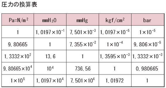
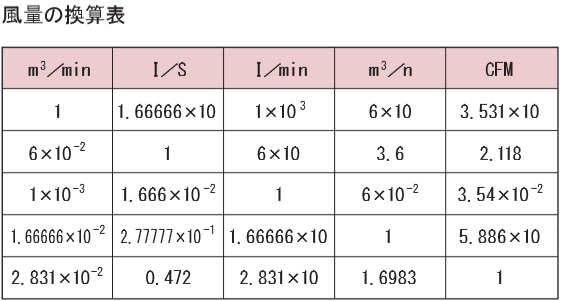
Hydrostatic Pressure – Air Volume Unit Conversion Table
In our company, static pressure = Pa and air volume = m3/min are used as units for static pressure-air volume characteristics. If you want to convert to other units, please use the following conversion table.
Security Export Management System
Export-Restricted Cargo
Appendix 1 of the Export Trade Control Order defines export-controlled goods as weapons Z (Paragraph 1), cargo with a high probability of being used in the development and manufacture of weapons of mass destruction such as nuclear weapons, biological and chemical weapons, missiles, and conventional weapons (Paragraph 2 ~ Paragraph 15), and cargo that is highly versatile but restricted when information is confirmed that the use will be used for the development of weapons, etc. (Paragraph 16 – Complementary Export Restrictions).
About the non-determination of our products
With regard to Paragraph 16 Supplementary Export Regulations, all electrical parts, mechanical parts, etc. fall under the scope of coverage, so all of our products also apply. For details, please check the website of the Security Trade Control Division of the Ministry of Economy, Trade and Industry, and make your own judgment as to whether or not an export license is required.